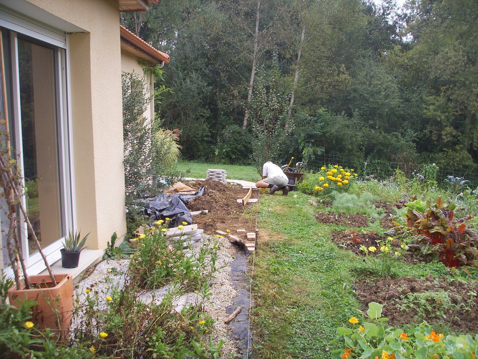
Getting there. My best side
It's not that obvious, but the border on the left of the path has been dug over by Laura and a lot of bind weed removed
40 pavers down and 100 to go.
14/10/14 Finished!
The odd, unrelated events in life, living in the Baronnies, in the south of France
Monday, 29 September 2014
Tuesday, 9 September 2014
Deck jet wash
About 2 hours to do about 3/4 of the deck, with about 200L of stored water.
25/10/14 another 90 minutes and ~250L of stored water to finish.
25/10/14 another 90 minutes and ~250L of stored water to finish.
Friday, 5 September 2014
Arnova 10d g3 tablet
Gravity played that trick. The one where it moves objects from the sofa to the floor. Or maybe it was the cat. Either way, the large power plug wrenched the internal connector, pulling the +ve pin off the mobo. I'd tried to solder this back on without removing the pcb, but it only lasted days.
And the reason I didn't want to remove the mobo? The battery, speaker and back light are soldered on. You'll need a 50W soldering iron to get the battery off, as the lands are large.
Once the pcb was off I tried to repair the connector - and I sort of succeeded by putting a bridge in place and a wire to hold the plastic together. I could not melt the solder lands even with a 50W fine tipped iron, so ended up attaching the wire to the adjacent SD card. I could have used a hot air SMD gun, but that was in the cupboard. So you'll need a large iron if you plan to change the connector.
The back two pins that are bridged are the unused normally closed and open bits to detect the plug insertion. I've marked the top side of the pcb where the +ve goes through to and will hard-wire the connector without removing the mobo if I need to again.
The type B mini-usb looks favorite for modifying for power in. It certainly won't accept charge. However, the 'power in' pin 1 is connected somewhere (measure 15k to 0V), so I didn't want to disconnect it and re-purpose it as a power in - it's also a bigish plug.
I cracked the top glass cover when taking the case apart and I wasn't being aggressive. It's visual and it all works ok. C'est la vie.
Tuesday, 2 September 2014
Subscribe to:
Comments (Atom)


